MDS satellite attitude control documentation
In this page, the main ways Atittude propagation and control is done in MDS will be explained. In MDS, spacecraft attitude behavior depends on whether the satellite is configured as a rigid body or a non-rigid body during creation. This configuration determines how the spacecraft orientation can be controlled within the simulation.
Rigidbody case
When rigid body 6-DOF simulation is enabled, spacecraft attitude is governed by the physical dynamics model. In this configuration, the spacecraft orientation cannot be directly set by most pointing modes or controlled in the UI.
Instead, the spacecraft attitude must be controlled through torques and rotational dynamics.
In rigid body mode, a torque can be directly applied ot the satellite using these functions:
mds_api.apply_thru(sat_name: str, thrust: list[float], torque: list[float], inertial: bool=False)apply_torque(sat_name: str, torque: list[float], inertial: bool=False)
These functions allow the user to apply external torques for the next propagation step in ICRF or the body-frame. That affect the spacecraft's angular acceleration, enabling the implementation of custom attitude control algorithms such as PID controllers, reaction wheel simulations, or other control systems.
This configuration is typically used when testing realistic spacecraft attitude dynamics or control systems.
To control the attitude rigidiy of the satellite, you can also set the Inertia Tensor using the function set_inertia_tensor(sat_name: str, inertia_tensor: list[float])
Non-rigidbody case
In the non-rigid body configuration, all pointing modes (mentioned below) are available and can be freely used. In this mode, spacecraft orientation is handled directly by the simulation environment rather than by a full physics-based rigid body model.
This configuration is particularly useful for: - rapid scenario prototyping; - mission concept demonstrations; - early-stage algorithm development;
Additionally, when rigid body dynamics are disabled, spacecraft attitude can also be controlled directly from the MDS UI. Users can select the pointing mode from dropdown menu and assign targets without needing to implement control algorithms. Because the orientation is set directly, this mode provides a simplified but highly flexible way to test mission logic, set up and test camera views, model communication or power subsystems.
Pointing Modes
As of MDS 1.5.0, the simulation environment supports nine different pointing modes for non-rigidbody case. These modes define how the spacecraft attitude controller determines the orientation of the satellite body relative to external objects or reference frames.
You can select the pointing mode in the UI via the satellite control window
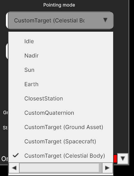
The available pointing modes are:
- Idle - sets pointing to idle. This mode could be utilized than attitude control is not required.
- Nadir - sets pointing to the central body nadir. This mode could be utilized for planet or other celestial body observation mission.
- Earth - sets pointing to an Earth center. This mode is useful then mission required pointing to Earth e.g. to facilitate telemetry and scientific data transmission back to earth.
- Sun - sets pointing to the Sun center. This mode is typically used for simulation of satellites power subsystem charging and discharging.
- ClosestStation - sets pointing to the closest ground station. This mode is useful then you ant to transmit telemetry and scientific data to closes available ground station.
- CustomQuaternion - sets pointing to a specified custom quaternion. This mode could be used by more advanced custom spacecraft attitude controller.
- CustomTarget (Ground Asset) - sets pointing to a selected ground station.
- CustomTarget (Spacecraft) - sets pointing to a selected spacecraft.
- CustomTarget (Celestial Body) - sets pointing to a selected celestial body.
API non-rigid body control Functions
1. Setting pointing mode
mds_api.set_pointing_mode(
    sat_name: str,
    mode_name: str,
    target_name:str | None = None,
    target_type:str | None = None,
    pointingQuaternion = None
) -> bytes:
Sets pointing mode for the selected satellite.
Arguments:
sat_name(str): name of the satellite.mode_name(str): name of the pointing mode.target_name(str or None): Name of the target object. Only relevant forCustomTargetmode. If not specified, the target is unchanged.target_type(str or None): Type of the target. Can beGroundAsset,SpacecraftorCelestialBody. Defaults toGroundAsset. If not specified, Target type remains unchanged.pointingQuaternion(list[4]): Quaternion in form [x,y,z,w], only relevant forCustomQuaternionpointing mode.
2. Setting pointing target
mds_api.set_pointing_target(
    sat_name: str,
    quaternion: list[float]
) -> bytes:
Set a custom pointing target quaternion for a spacecraft.
Arguments:
sat_name(str): name of the satellite.quaternion(list[float]): list of [x,y,z,w] quaternion values representing ICRF to body frame rotation.
This function also automatically sets pointing target to
CustomQuaternion
Reference frames
Main reference frame used for attitude control in MDS is ICRF (Sun-centered):
- Origin - Solar system barycenter (close to sun)
- Axes:
- Z - towards Earth North Pole at J2000
- X - toward vernal equinox at J2000
- Y - Right Hand Rule
The transformation R vector transforms from body to ICRF.*